
|
Height Control System.doc Size : 3059.5 Kb Type : doc |
|
|
Talaria.doc Size : 42 Kb Type : doc |

|
Waves.xls Size : 111.5 Kb Type : xls |

|
XFOILInput.txt Size : 1.753 Kb Type : txt |
|
|
xfoilSection.xls Size : 77.5 Kb Type : xls |
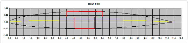
Bow Foil
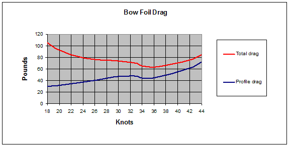
A design objective is a takeoff speed less than the boat’s the hump speed, and secondarily, to maximize top speed. The design options for the bow foil are: foil area, aspect ratio, thickness, and section. The material is unidirectional carbon fiber with a fiberglass core.
The bow foil is very lightly loaded at the beginning of a takeoff run. As the stern lifts it becomes fully loaded. Consequently the lift - area requirement of the bow foil occurs at a higher speed than that of the stern foil. Thus it can be more heavily loaded. In addition, for pitch stability, the derivative of lift versus angle of attack should be lower for the bow foil than the stern. For a take off speed below hump speed the loading of the aft foil is 577#/ft2 . The bow foil’s loading is 619#/ft2 .
The bow foil is articulated in angle of attack. It is pivoted on a shaft just forward of its center of loading. The size of the shaft and thus its bearing block are dictated by 1700# loading on the bow foil. The bearing block’s thickness is 1.25”, constraining thickness of the bow foil.
Within the constraints of loading, thickness, and material stiffness, the section was designed with XFOIL, ncrit =3.
The formula y(x)= t xa (1-xb) was used to generate the symmetric sections.
Where y(x) = +/- thickness, x = cord (0-1), t = thickness parameter (.1045), a (.52) and b (2.1) are shape parameters. Camber was generated using the same formula, (.0245), (.54), (2.4).
With a minimum drag at maximum speed section the center thickness determined the center cord, 11.75”. With that and stiffness the span and aspect ratio were largely determined.
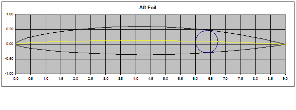
Aft Foil
The aft foil performs two functions, roll authority and lift. The design objective to keep the foils within the beam of the boat limits roll authority. To maximize roll authority the full span flaps are 1/3 of cord. With the span at the boat’s beam, 8’, and the takeoff speed below hump speed the foils area is determined. Its loading is 577#/ft2, cord 9”, total span 95”.
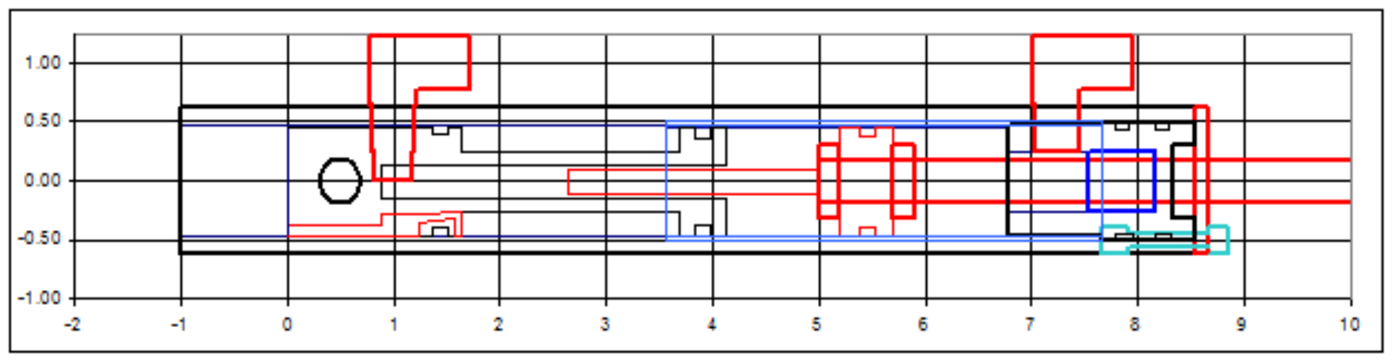
The aft foil has hinged flaps with 3 hinge bearings, each end and near the center. The flaps are actuated from the center pod by hydraulic cylinders with a 2” throw actuating a 2.6875” bell crank. The torque is thus transmitted through the flaps from the center to the outboard end. Carbon fiber inboard flaps were found not to have the necessary torsional stiffness. Welded 316 stainless steel inboard flaps were constructed. The outboard flaps are of carbon fiber.
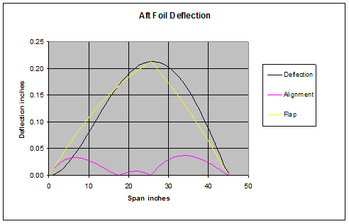
A design requirement is that flap - foil interface not significantly diverge. Thus the bending of the foil versus the flaps must be minimized. This imposes a stiffness requirement on the aft foil. Below, the purple line shows the absolute divergence of the foil and flap with a plus one G load. The maximum divergence is .0373”. Also, the center hinge is located at 25.55” of the 45.4” span to minimize the divergence.
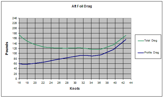
As with the bow foil, the design objective is takeoff below hump speed and then the maximization of top speed. To maintain pitch attitude over the speed range the flaps are biased as a function of speed. Relative to 36 knots, the flap bias at takeoff is 3.3degrees down.
Give the loading, flap setting, span, and takeoff speed the cord can be determined. Section thickness, with a small impact on drag, and carbon fiber skin thickness (cost) are traded to make the foil thickness choice. Its thickness is .95” and cord 9”. Using the same section generating formula as the bow foil its symmetric section parameters are: .0990, .53, 2.1. Camber parameters are: .026, .48, 2.0.
The foil has 10 degrees anhedral. This is primarily to lower the foil tips to reduce the likelihood that they will broach during a banked turn in waves. It also increases roll authority slightly.
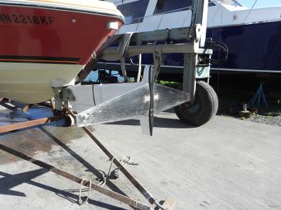
Foil Construction
The dominant structural requirement for Talaria's struts and foils of is longitudinal stiffness and sometimes strength. The loads and dimensions are such that the unidirectional carbon fiber must be thick, generally more than .25”. Unidirectional carbon fiber is very dense and does not infuse well without a flow medium. An imbedded flow medium, of course, reduces the fiber content of the layup. I found via experiment that I could not reliably infuse unidirectional carbon thicker than .125”.
The layup procedure I adopted was to set up the mold for infusion, hand layup the carbon fiber with resin, lay in the woven fiberglass core dry, seal the mold, establish the vacuum and let the excess resin infuse from the carbon into the core. Then infuse the remaining dry core.
It worked best to layup each side of the strut or foil separately and glue them together after the initial cure.
Aft Hydraulic Cylinders
The aft hydraulic flap cylinders have an ID of .94”, rod of 3/8”, and a throw of 2”. They include an embedded position sensor. The sensor is a coil of 6000 wraps embedded in epoxy around an Acetal spool. A 1600 Hz square wave, at +/- 15 volts, drives the coil. The circuit terminates with a 500 ohm resistor to ground. The square wave is attenuated by a steel rod attached to the cylinder’s piston rod. As the piston is retracted the attenuation increases. The attenuated wave is rectified, smoothed, and read by the flight computer’s analog digital converter. The piston slides in a stainless steel (SS) sleeve pressed onto a 316 SS cylinder end block. The block holds an 1/8” pipe flare fitting, a bronze bushing, and the rod seal. The piston is of Acetal. The SS sleeve overlaps the end O-ring of the spool. This seals the hydraulic oil from the coil. At the other end of the coil is an O-ring that seals the coil from the outside – water. The body of the cylinder is carbon fiber epoxy rather than a metal. The coil’s transmission is attenuated by metal, thus its output variation is would be decreased by using a metallic cylinder body.
Bow Hydraulic Cylinder
The bow foil actuation cylinder has an ID of 1”, rod of ½”, and throw of 2”. It is machined from an aluminum block and anodized. Its design is similar to the aft cylinder but does not include the coil spool.